Brand Name: Ilamps
Model Number: ILA-05
Place of Origin: China
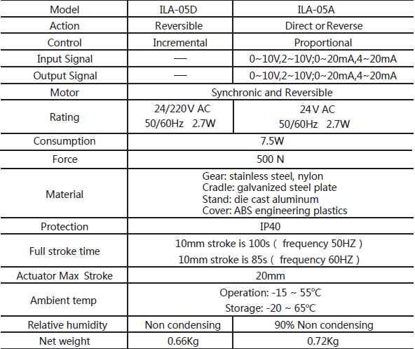
ILA-05A, accepting 0(2)~10V DC or 0(4) ~20m A DC c ontro l signa l and
providing proportional control.
ILA-05D, providing incremental control, assembled with reversible motor.
Specifications
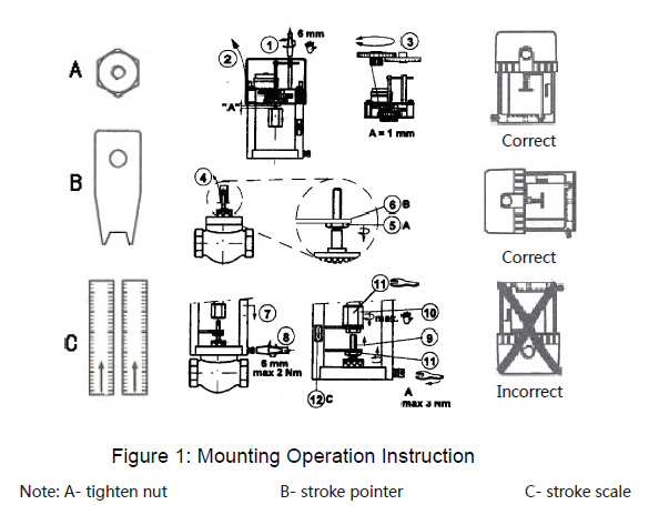
Mounting
-Mounting position is up right to horizontal. It is recommended that the
valve be mounted in the up right position in accessible location.
Sufficient clearance must be allowed for actuator maintenance or detaching
Attention
1. The actuator should be protected from the dipping water that could enter
the housing and damage the mechanism or motor.
2. The actuator must not be covered with insulating material.
3. Disconnect the power supply before repairing and maintenance are made
to avoid personal injury and machine damage.
4. Do not tough or disconnect wire when power is on.
Wiring Diagram
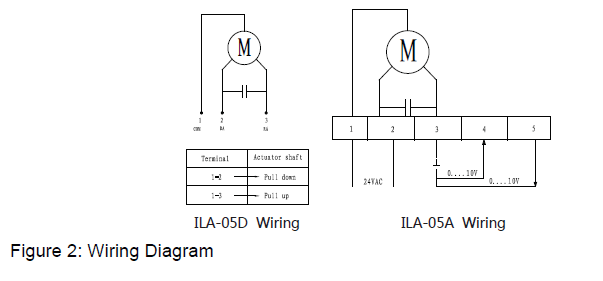
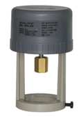
ILA-05A Valve Actuator
S1 / S2 Dial Switch Function Instruction
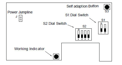
S1 Dial Switch Setting
• Position 1 :”OFF” is for voltage output signal,”ON” is for current output signal;
• Position 2 :”OFF” is for voltage input signal,”ON” is for current input signal;
S2 Dial Switch Setting
Position 1:OFF:equivalent-linearity flux characteristic,
ON:Equivalent-percentage characteristic;
Position 2:OFF:Input/Output signal start point is 0 (0-20mA or 0-10V)
ON:Input/Output signal start point is 20%(4-20mA or 2-10V)
Position 3:OFF:RA Model(Control signal increase, actuator central shaft going up)
ON:DA Model(Control signal increase, actuator central shaft going down)
Position 4:OFF:When voltage input signal is cut, the actuator central shaft will running to the top;
When the current input signal is cut, the actuator central shaft will running to
the bottom;
ON:When voltage input signal is cut, the actuator central shaft will running to the bottom;
When current input signal is cut, the actuator central shaft will running to the bottom;
5. Actuator for Adjusting
According Mounting Diagram for actuator/valve,firstly follow the requirements to
finish setting the dial switch,then connect the power input/output signal wire,push
“self-adaptation” button over 3 seconds,you can check the shaft operating up to the top,then operating down to the bottom,the indicator flashing at same time。About after 200 seconds the indicator stop flashing,,in the time, the electronics control valve and the valve body self adaptation process finish,valve connect to the actuator signal
cooperation work finish.
Notice:The whole processing only need to be connected 24VAC power
supply,it is no matter with the input/output signal.
Warning:Every time for inputting or outputting signal range need to be
repeat the self adaptation process.


- Product Listing Policy - Intellectual Property Policy and Infringement Claims
- Related Links
- Privacy Policy
- Terms of Use
ICP License: 浙ICP备2023052164号 © Coowor.com. All rights reserved.
Tel: +86 10 65447649 E-mail: coowor@coowor.com
Copyright © Hangzhou Coowor Network Technology Co., Ltd. All Rights Reserved.